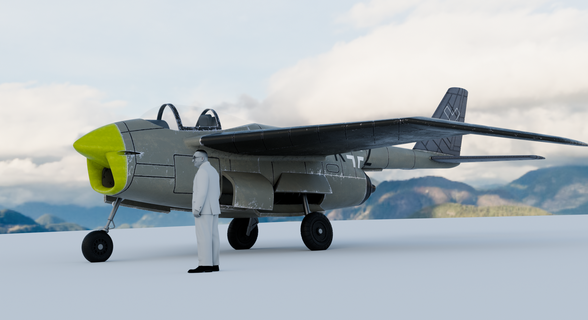
Henschel Hs 132
A Technical Analysis of the Single-Engine Close-Support Jet

The Henschel Hs 132 represents one of the most unconventional close-support aircraft concepts to reach the prototype stage during the Second World War — combining a prone pilot position, a dorsally-mounted turbojet, and a Mistelschlepp towing capability into a single coherent, if never operationally tested, weapons system.
Overview and Design Concept
Officially designated Einmotoriges Nahkampfflugzeug — single-engine close-support aircraft — the Hs 132 is a cantilever mid-wing monoplane of mixed metal and wood construction. Its most immediately striking feature is the dorsal installation of a BMW 109-003 A 1 axial-flow turbojet, positioned on the upper fuselage spine. This configuration was a direct consequence of the aircraft's second defining characteristic: the pilot flies in a fully prone position, lying face-down on an armored couch.
The primary operational role defined in the specification is precision dive-bombing against point targets at short approach distances — specifically against armored vehicles in land warfare and shipping targets at sea. The document explicitly notes that fixed gun armament was not planned in the initial configuration due to the thrust limitations of the BMW 003 engine, with installation deferred until a higher-thrust powerplant became available.
"Das Flugzeug Hs 132 soll vorwiegend zum Bombenangriff auf Einzelziele bei kurzen Anflugstrecken Verwendung finden, etwa zur Bekämpfung von Panzern u.dgl. in der Landkriegführung, zum Angriff auf Schiffsziele über See."
The aircraft is designed to structural stress group Beanspruchungsgruppe H 5, with a safe ultimate load factor of n A sicher = 10 and a maximum permissible dive speed of 950 km/h. The performance figures anticipated from an upgraded engine were considered promising enough for the document to note that the flight characteristics of the prototype showed potential for further development as a fighter aircraft.

Airframe
1. Fuselage (Rumpf)
The fuselage is a light-alloy monocoque shell structure ( Leichtmetall-Schalenbauweise ) divided into a forward section ( Vorderteil ) and a rear section ( Hinterteil ).
Forward section. The front fuselage houses the pilot's cockpit with his complete armored enclosure, all flight instrumentation, controls, and the nose landing gear. The pilot lies on a padded prone couch ( gepolsterte Liegewanne ) fabricated from armor plate; beneath it is the nose gear bay. The chest portion of the couch is fixed; the rear is hinged and serves as the primary entry and exit hatch, operated hydraulically and — in an emergency — by compressed air from a dedicated steel bottle. A separate bailout hatch is installed on the upper fuselage surface for belly-landing evacuations.
The armored enclosure from the midpoint of the breast shield to the windscreen provides protection against 2 cm explosive shells. A Plexiglass cupola seals the forward fuselage face. Electrical equipment and foot controls occupy the lateral and rear cockpit walls; hydraulic lines, fuel fittings, and control runs are routed in a sub-floor space beneath the pilot's legs.
Rear section. Separated from the cockpit by a firewall bulkhead, the rear fuselage divides internally into three structural bays. Bays one and two are entirely occupied by the two fuel tanks, topped by a common removable cover panel. The firewall simultaneously serves as the engine oil tank. The wing center spar box is carried between the tanks in a double frame, and the flap drive is located aft of the second tank. The third bay houses FT radio equipment and control runs, accessible via a ventral hatch. Skin coverage in the tail zone is applied only to the lower half of the structure.

2. Landing Gear (Fahrwerk)
The main gear consists of two single-strut retractable units that retract hydraulically inward into the wings, using 70 × 17.5 cm wheels. The nose gear — a single-leg unit with a fork — retracts rearward into the fuselage. On hydraulic failure, the main gear mechanically unlocks and falls free under gravity, held in extension by a pre-tensioned spring. The nose gear is extended by compressed air as a backup system.
3. Tail Unit (Leitwerk)
The horizontal stabilizer is a one-piece structure with a steel main spar and wooden planking. Both elevators are built entirely in wood and carry a trim tab ( Hilfsruder-Ausgleich ). Two end-plate vertical fins, attached at the stabilizer tips, carry the wooden rudders. The ailerons are simple camber flaps ( Wölbungsklappen ) with balance tabs, structurally identical to the other control surfaces.
4. Control System (Steuerung)
The control column, positioned to the right of the pilot's elbow, drives both pitch and roll. The pitch circuit runs as a closed cable system from a bell-crank at the stick shaft through the front fuselage; through the rear fuselage the cable is duplicated for safety, driving a coupling shaft in the tail that actuates the elevators via a spring-loaded force-sensing mechanism. When stick force exceeds the spring preload, the balance tab deflects as a servo tab, reducing pilot effort. Trim is handled independently via the standard unitary trim device ( Einheitstrimmgerät ) operating through torque shafts, cables, and a self-locking jackscrew in the tail cone.
The roll linkage couples the stick to the flap drive, causing ailerons to deflect in conjunction with the landing flaps during takeoff and landing. Landing flaps are hydraulically actuated in the fuselage, with deflection equalized between sides by a mechanical coupling. Rudder control runs from suspended, parallel-mounted adjustable pedals via a rocker arm and cable to the rudder panels.
5. Wing (Tragwerk)
The wing is a single one-piece structure with a steel main spar and wooden planking. Multiple wooden ribs transmit transverse loads. The full wing, excluding the main gear bays, acts as a closed torsion box. Landing flaps are simple camber flaps in the same wooden construction as the other control surfaces.
6. Hydraulic System (Öldruckanlage)
An engine-driven oil pressure pump draws fluid from the reservoir and delivers it at 75–90 atü. A bypass valve diverts the pump to return when the accumulator reaches operating pressure; when pressure drops, the pump recharges the system automatically. Hydraulic consumers: main landing gear, landing flaps, and the entry hatch.


Powerplant
Engine: BMW 109-003 A 1
The installed engine is the BMW 109-003 A 1 turbojet ( TL-Triebwerk ). Static thrust is 800 kp. The engine bearer is an upward-open frame at the engine's center-of-gravity plane, rigidly bolted to the fuselage at three attachment points — two rigid joints forward, and a pendulum strut ( Pendelstütze ) aft. The cowling consists of two half-shells bolted to three longitudinals and two frames.
| Condition | Thrust |
|---|---|
| Static (Standschub) | 800 kp |
| Full throttle at 0 km, v = 200 m/s | 710 kp |
| Full throttle at 6 km, v = 200 m/s | 440 kp |
Fuel System
Fuel is stored in two armored magnesium-alloy tanks in the rear fuselage (forward draw tank plus aft transfer tank), arranged in a dual-feed system. Two tank pumps deliver fuel through a valve battery and two filters to the engine. The rear tank is transferred forward by a single pump; on electrical failure, the engine's own suction can draw directly from either tank. Tank contents are displayed on the instrument panel with a low-level warning lamp. The fuel cock has three positions: Brandhahn zu (shut-off), Betriebsstellung (normal pressure feed), and Notschaltung bei Elektrik-Ausfall (emergency electrical bypass).
Equipment and Systems
Flight Instrumentation
Instrument panel (left cockpit): heated pitot tube at wing tip, variometer, airspeed indicator, remote compass system, clock, and turn indicator. Master compass in the rear fuselage; the turn-and-bank indicator can optionally be positioned in front of the armored windscreen.
Engine Monitoring
Panel (right cockpit): RPM indicator, oil pressure gauge, oil temperature gauge, fuel pressure gauge, exhaust temperature gauge, fuel quantity indicator with selector switch, and low-level warning lamp.
Electrical System
A 2,000 W generator driven off the engine supplies the 24 V DC network. At engine-off: a 7.5 Ah battery. Individual loads are protected by self-resetting circuit breakers. Primary consumers: FT radio, bomb release, fuel pumps, and electrical instruments. An external ground-power socket enables engine starting and pre-flight checks.
Radio and Navigation
The onboard radio ( Bordfunkanlage ) covers air-to-ground and air-to-air communication. A direction-finding attachment ( Zielflugvorsatz ) enables homing on DF ground beacons. Equipment is installed in the rear fuselage, accessed through a ventral hatch; operating frequencies are pre-set on the ground and the system is remotely operated from the cockpit in flight.
Safety and Survival
Oxygen system (O₂ bottle, lung, mask) for high-altitude operation. Lap belt for belly-landing protection. Parachute harness. First-aid kit at the escape hatch cover. Built-in signal pistol ( Leuchtpistole ).
Armament
Drop Armament
Locks on the fuselage underside accommodate the following loads, released electrically via the bomb button on the stick. An emergency jettison pull releases all stores simultaneously. The bombing sight is a Revi ( Reflexvisier ), mounted in the Plexiglass cupola in front of the armored windscreen.
| Configuration | Description |
|---|---|
| 6 × SC 70 | Six 70 kg general-purpose bombs |
| 1 × SC 250 | One 250 kg general-purpose bomb |
| 1 × SC 500 | One 500 kg general-purpose bomb |
| 1 × SC 1000* | One 1,000 kg bomb (shown in cutaway drawings) |
* The SC 1000 option appears in the classified cutaway drawing (Fig. 2) but is not listed in Baubeschreibung Nr. 66 itself.
Gun Armament
No gun armament is specified for the initial production configuration — explicitly due to the thrust limitations of the BMW 003 engine. Installation is stated to be intended in conjunction with a higher-thrust powerplant in a subsequent variant.
Mistelschlepp — Composite Tow Capability
An appendix to the Baubeschreibung describes the use of the Mistelschlepp (composite towing) technique to substantially increase bomb and fuel load beyond what the landing gear structural limit would permit in a conventional wheeled takeoff. In this mode the landing gear is replaced by a skid arrangement, eliminating both the gear weight penalty and its structural loading constraint. Two mission profiles are defined.
Einsatzart I. The Hs 132 — loaded with 2 × BT 700, or 1 × SC 1700, or SD 1800 — is towed to approximately 4 km altitude by a carrier aircraft, then released at a minimum airspeed of approximately 280 km/h. The Hs 132 proceeds at full throttle to the target, releases its bomb load (1,400 kg), and returns to base under reduced power. Usable fuel: 600 kg.
Einsatzart II. To achieve significantly greater range, the carrier aircraft tows the Hs 132 close to the target before release. After separation, the Hs 132 flies approximately 5 minutes at full throttle, attacks, and returns under reduced throttle. Bomb load: 1,800 kg; fuel: 900 kg (or up to 1,200 kg if the landing gear is deleted entirely).
Technical Data (Datenblatt Nr. 168)

Principal Dimensions
| Parameter | Value |
|---|---|
| Span (Spannweite) | 7.8 m |
| Length (Länge) | 8.8 m |
| Height (Höhe) | 2.95 m |
| Wing area (Flügelfläche) | 14.7 m² |
| Aspect ratio (Streckung) | 4.13 |
Weight Breakdown (Gewichtsaufstellung)
| Group | Sub-items | Mass |
|---|---|---|
| Fuselage (Rumpf) | Cell + equipment + armor (105 kg) + armored glass (73 kg) | 485 kg |
| Landing gear (Fahrwerk) | Main wheels, struts, nose gear assembly | 274 kg |
| Hydraulic system | — | 60 kg |
| Tail unit (Leitwerk) | Horizontal (38 kg) + vertical (17 kg) | 55 kg |
| Control system (Steuerung) | — | 48 kg |
| Wing (Tragwerk) | Main spar (74 kg) + structure and skin (286 kg) | 360 kg |
| Powerplant (Triebwerk) | Engine dry (570 kg) + mount/firewall/cowling (57 kg) + tanks w/ medium armor (118 kg) + lines/linkage (32 kg) + residual fill (7 kg) | 784 kg |
| Equipment (Ausrüstung) | Standard (131 kg) + bomb sight (72 kg) | 203 kg |
| Empty weight (Rüstgewicht) | ~2,269 kg | |
| Payload (Zuladung) | Fuel 663 kg + oil 18 kg + crew 90 kg + bomb load 500 kg | 1,271 kg |
| Gross flight weight (Fluggewicht) | 3,500 kg | |
Performance
| Parameter | With Bomb Load | Without Bomb Load |
|---|---|---|
| Maximum speed (Höchstgeschwindigkeit) | 635 km/h at 4 km | 785 km/h at 6 km |
| Cruise speed with thrust | 547 km/h at 2 km | 713 km/h at 7 km |
| Rate of climb at sea level | 9.7 m/s | 17.7 m/s |
| Time to 3 km | 6.2 min | 3.3 min |
| Time to 5 km | 13 min | 6 min |
| Service ceiling (Dienstgipfelhöhe) | 7.5 km | 11.2 km |
| Maximum range | 530 km at 80% throttle at 6 km altitude | |
| Takeoff run (Rollstrecke bei Start) | 1,250 m | |
| Landing speed (at 2,420 kg) | 154 km/h | |
Assessment
The Henschel Hs 132 represents a technically coherent, if highly unconventional, approach to a first-generation jet-powered close-support aircraft. The prone pilot configuration, the dorsal engine installation, and the Mistelschlepp capability together reflect a systematic effort to extract the maximum operational utility from the comparatively modest static thrust of the BMW 003 engine — an engine whose 800 kp static thrust compares closely with that of the contemporary Junkers Jumo 004 B at 900 kp.
The structural design — steel main spars, wooden secondary structure, light-alloy monocoque fuselage shell — is consistent with German wartime materials practice imposed by aluminium shortages. The load factor of 10 and the 950 km/h limiting dive speed indicate that the structural specification was genuinely demanding, appropriate for an aircraft whose primary mission demanded a steep dive-bombing approach. The explicit provision for a higher-thrust engine in a gun-armed variant demonstrates that Baubeschreibung Nr. 66 describes an initial production baseline rather than a terminal design.
Three prototypes were under construction at Schönefeld when Soviet forces reached the factory in May 1945. None flew. The V1 was captured substantially complete; subsequent examination by Soviet engineers has been documented but no operational evaluation followed. The aircraft remains one of the more technically sophisticated of the unrealised German jet programmes, and the only one to combine the prone-pilot concept with a defined and documented operational doctrine at this level of design maturity.


Check out LEMKIT's 1/32 model kit